 |
By: Olivier de Broqueville
November 2002
NEW EDITION: (Some changes to the PCB and program to solve unstable PIC to PC communication)
|
Initially, this project was built to log the level of radioactivity on a long period of time. At the time of Chernobyl, I built 2 Geiger counters. One home developed and one based on the Velleman kit (ref. K2645 and View of the Kit). After years, I found back this little Velleman counter and decided to develop a Data Logger for it. As this project is basically counting pulses during a certain amount of time and then doing some maths on it before displaying the results and storing them in EEPROM, it will be presented as stand alone. It is up to you to modify the program or the design to reach your own needs.
The program is not optimized and uses nearly the entire code space. This explains why the LCD messages are so short. TEXT burns a lot of code space...No doubts that it could be improved. If one of you develops a better version, I would be pleased to add it to this project. After all, the purpose of this site is to suscitate experimentation.
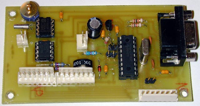
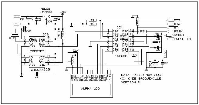
This project is based on the 16F628. Although this PIC can run without external Xtal, it was chosen to use one as, it its first version, the Data Logger did not dispose of an RTC. This is why a 4Mhz Xtal is used. If you need more I/O, you could imagine to drop the Xtal, to use internal clock and to reuse the liberated pins for other purposes. The MCLR pin( Pin 4) is not used in MCLR configuration as I needed one more IO for Button 3.
The Project includes also a RTC (Real Time Clock) PCF8583 (data sheet) and an EEPROM (24LC256).
The Project is able to interpret data acquired through 2 types of Geiger Tubes : ZP1400 and ZP1310 . As GEIGER Tubes are using high voltage, and to protect the PIC, a protection is built around PORTB.6
The main notions used in the project are:
Even if written last year, the enclosed program was recompiled for PROTON + V2.1
 |
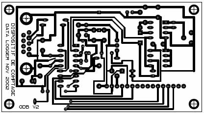
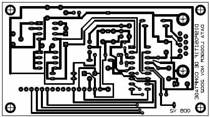
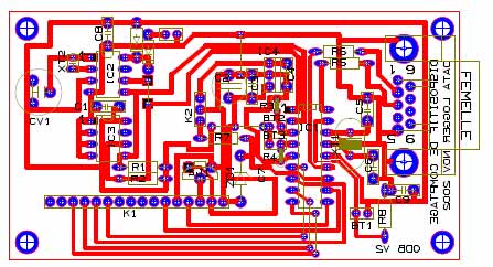
Board Print in TCI3.1 format (see How To concerning PCB design to get and use TCI freeware)
 |
 |
 |
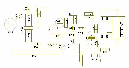 |
| R1-R2 : 4.7K | IC1 : PIC 16F648A |
| R3-R4 : 10K | IC2 : PCF8583 |
| R5-R6-R7 : 1K | IC3 : 24LC256 (or depending on how much data is to store) |
| R8 : 10K | |
| IC4 (REG) : 78L05 | |
| C1-C3-C4-C7-C8-C9 : 100nF | |
| C2 : 470uF 16V | Xtal 1 : 4Mhz |
| C5-C7 : 33pF | Xtal 2 : 32.768 Khz |
| CV1 : 3-33pF | |
| AJ1 : 10K | |
| ZD1 : Zener 4.7V 400mA | RS232 DB9 female |
| Alphanumeric LCD 2x16 car. compatible PROTON |
In fact, to fully be able to use the Data Logger, you need 2 programs. One file for the PIC and one small VB Application to download the data and save them on a PC. The PIC program has the ability to detect a download request made by the PC application.
The Data Logger project is divided in two part. The recorder itself, composed by the PIC application in charge of counting pulses per unit of time, calculating averages and storing data in EEPROM with a time stamp. As DATA reside in EEPROM, they can stay there for years. But this is not really what is expected for. To really exploit the data, it has to be possible to export them on a PC. The second part of the project includes therefore a small Visual Basic application, able to initiate data transfer from the PIC application and to convert the data flow in a file (.txt type)
The data structure is quite simple : xxxx;dd/mm;hh:mm;yyyy where:
xxxx : Data sample number
dd/mm : Date in dd/mm format. The year is not foreseen as the RTC PCF8583 does not control year in a standard way. It is possible to add this capability but it will 'burn' more code space from the PIC. The actual program is already filling nearly fully this space.
hh:mm : Time in hh:mm format. Seconds are not included but could easily be.
yyyy : Data
The length of the record can vary as the data sample and the data can have a length from 1 to 5 characters.
The resulting PC file is in TEXT format , and contain only the data.
Example:
| 1;27/05;09:55;13 2;27/05;10:55;12 3;27/05;11:55;14 4;27/05;12:55;13 5;27/05;13:55;11 |
The PIC Program (bas file):
After usual initialization, (RS232 is 9600,8,N,1 and RS MODE is false as the RS232 occurs without MAX232) the program initialize TIMER1 as a external counter (not synchronized with the Clock). This counter will increment for each pulse detected on PORTB.6. This port is not chosen per chance, it is THE port used by TIMER1 (see datasheet). TIMER1 will increment provided that interrupts are enabled.
PCF8583 is also initialized. The prototype did not have any backup battery for the RTC. This means that each time, it had to be reset. As the Battery Backup connector is well provided on the board, this could be adapted.
The MAIN routine is waiting for elapsed time. When reached, calculations are made and data are stored. It also waits to see if a "D" character is received on the RS232 Input. If yes, this means that the VB application is asking for Download. The RS232 routine sends a "U" (Upload). This is checked by the transfer VB application in order to be sure that it is valid DATA LOGGER data. The transfer ends when the RS232 routine sends a "E". All those control characters are removed from the resulting PC file.
Finally, the MAIN routine checks port pins dedicated to the 3 buttons. If depressed, the program enters in the MENU routine.
Some subroutines were also needed in order to convert data to the desired format on LCD and in the LOG.
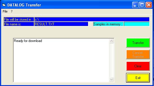 |
This Application is written in Visual Basic 6. It was created initially to be able to download the DATALOGGER memory (without resetting it) and to convert the data flow in a text file. As the delimiters are ';' it is easy to use those data in a Excel sheet
When a Download is asked, the VB application sends a 'D' ASCII character and retry till the PIC answers. A timeout will occur if the data logger does not answer within 10 sec..
There are basically no adjustment to do in this project. The only possible adjustment, if needed, is by adjusting CV1 to improve the time accuracy.
Developed by Olivier de Broqueville in November 2002
(Last edition 21/04/05)
Crownhill's Proton Plus Compiler is a part of the Proton Development Suite - A suite of British-developed applications enabling fast development of PICmicro's using the PICBASIC Language.
For more information on the Proton Development Suite, please visit www.picbasic.org
Please note that this project is published AS IS. No responsibility of the author in any cases can be invoqued. This project is for learning and entertainment purpose only. No vital application can be connected to it. As this project is published on a free and friendly base for the user site of PROTON +, it cannot be used in any condition for business or commercial use without explicit permission of the author.